 Čeština
 English
You are here
Rotary sensor with AS5048
Introduction
The original reason to develop this construction was an effort to design a better circuit with microcontroller of the same manufacturer like in the case of the new controller unit. Shortly after the first prototype with AS5045 chip I discovered that AS5048 chip has better availability, price and resolution. So the decision to design sensor with a newer chip was quite easy.
Schematic
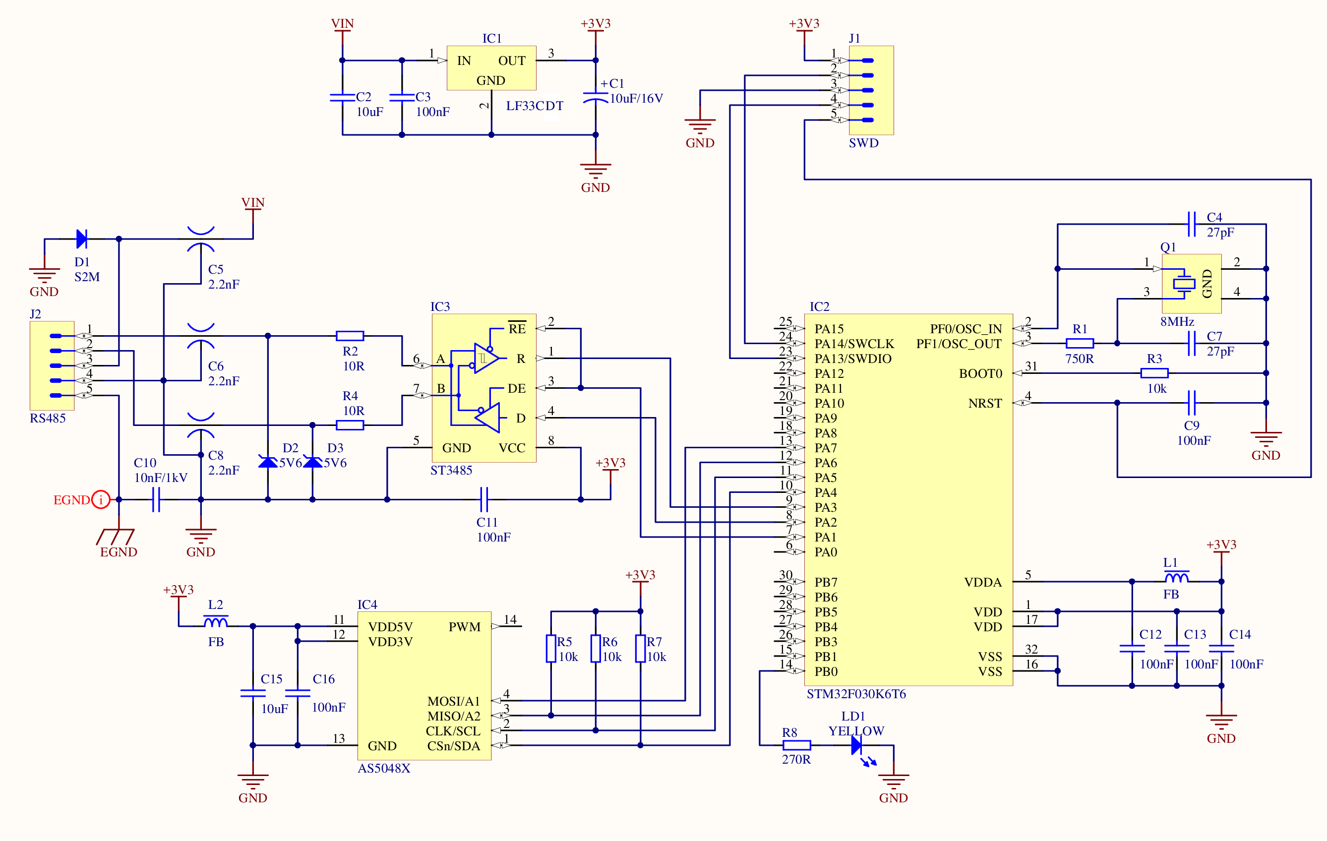
Schematic
Description
The chip AS5048 is available in two versions. AS5048A version has SPI interface, AS5048B version has I2C interface. The market availability of electronic parts is changing with time, so I decided to make a common circuit for both versions. The firmware detects the chip version automatically.
A power supply 3,3 V for all components is provided by LF33CV linear regulator with a tantalum capacitor on his output.
As a microcontroller, I chose a chip STM32F030K6 for the small size, good availability and price.
To keep the circuit simple and small I decided not to place the EEPROM. This type of memory is emulated in flash memory of the microcontroller.
Programming
The microcontroller can be programmed via the SWD interface. A ST-Link v2 compatible programmer can be purchased on eBay very cheaply. I placed on PCB a small connector to interconnect sensor with a programmer. It is a much better solution than a soldering in case of previous versions.
After the bootloader is successfully programmed, the LED will start to flash with fast frequency. This means that the device is in firmware programming mode. If the bootloader finds a valid application program, it will run after a short time.
The application firmware is uploaded via the RS-485 bus through the controller unit. The SWD interface is no longer used. The default sensor ID for the RS-485 bus is 254. The LED in application mode indicates the state of the magnetic field. If the magnetic field is OK, the LED is off.
Printed circuit board
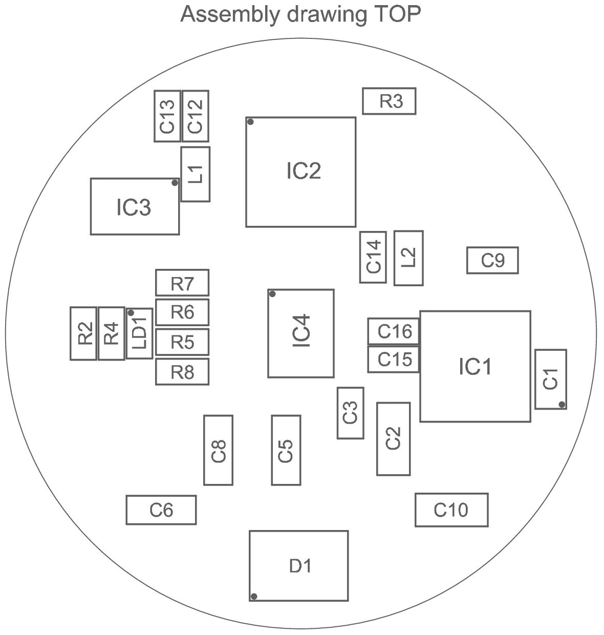
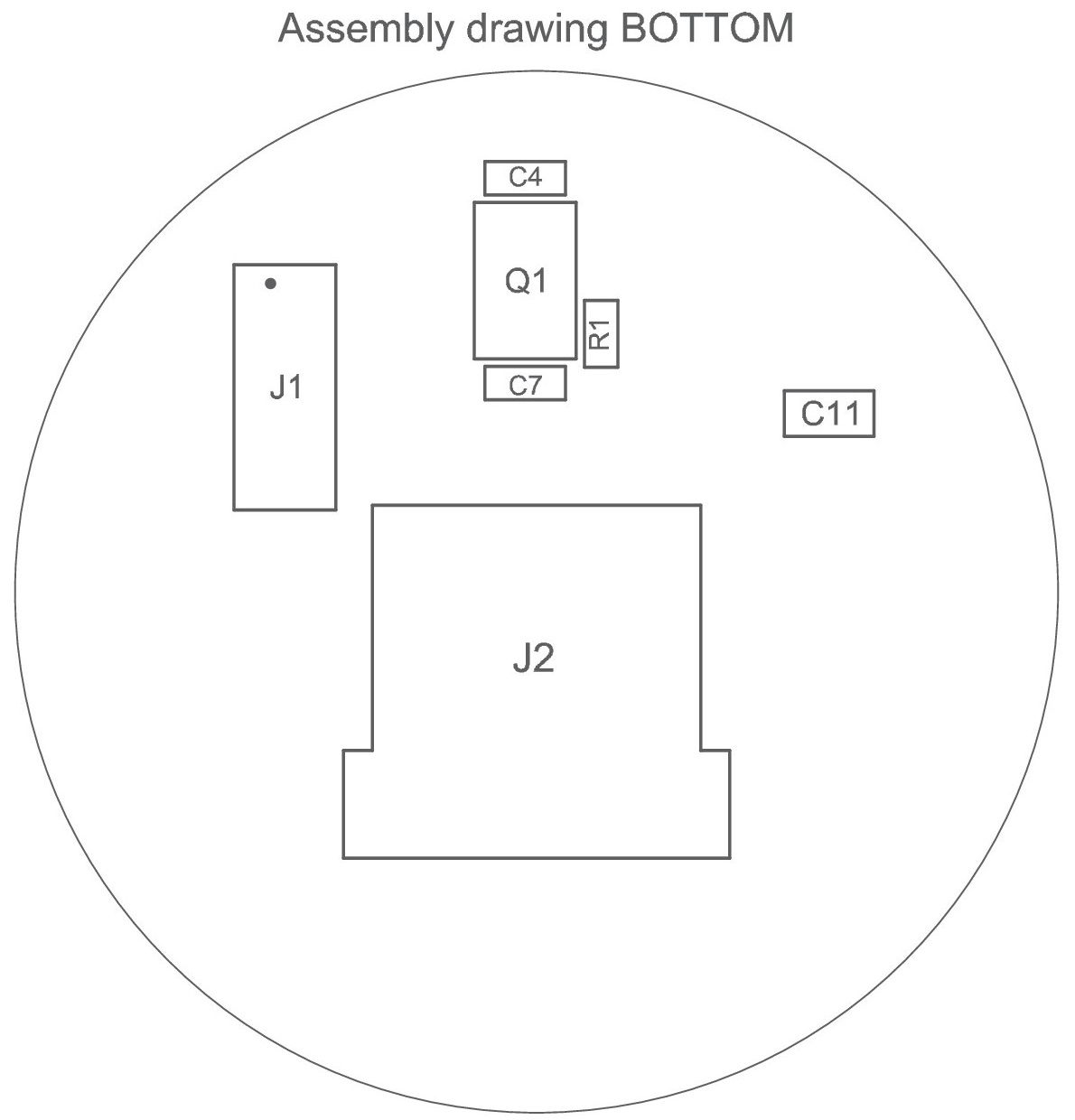
Assembly drawings
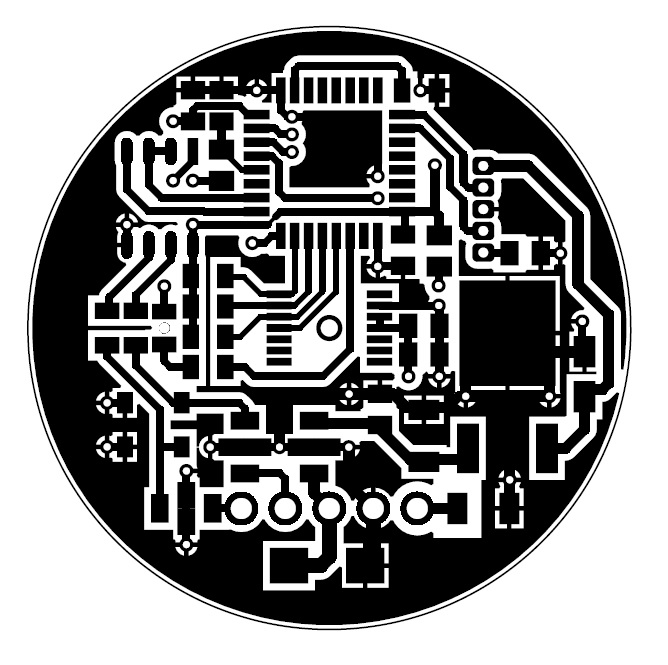
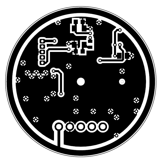
Board layouts - Diameter 34,9 mm
Bill of materials
| R1 | 750 Ω | 0805 |
| R2, R4 | 10 Ω | 0805 |
| R3, R5, R6, R7 | 10 kΩ | 0805 |
| R8 | 270 Ω | 0805 |
| C1 | 10 uF /16 V tantal | SMD-A |
| C2 | 10 uF /25 V X7R | 1206 |
| C3, C9, C11, C12, C13, C14, C16 | 100 nF | 0805 |
| C4, C7 | 27 pF | 0603 |
| C5, C6, C8 | Murata NFM3DCC222R1H3L | 1205 |
| C10 | 10 nF /1 kV | 1206 |
| C15 | 10 uF /10 V X7R | 0805 |
| D1 | S2M | SMB |
| D2, D3 | Zener diode 5,6 V | SOD-123 |
| L1, L2 | Ferrite bead | 0805 |
| LD1 | LED yellow | 0805 |
| Q1 | Crystal resonator 8 MHz | SMD 5x3,2x1 mm |
| IC1 | LF33CDT | DPAK |
| IC2 | STM32F030K6 | LQFP32 |
| IC3 | ST3485 | SO08 |
| IC4 | AS5048A / AS5048B | TSSOP14 |
| J1 | Mollex 53047-0510 | 1,25 mm pitch |
| J2 | Ninigi NS25-W5K | 2,54 mm pitch |
Assembled sensor and models

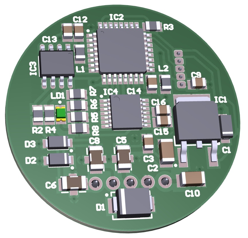
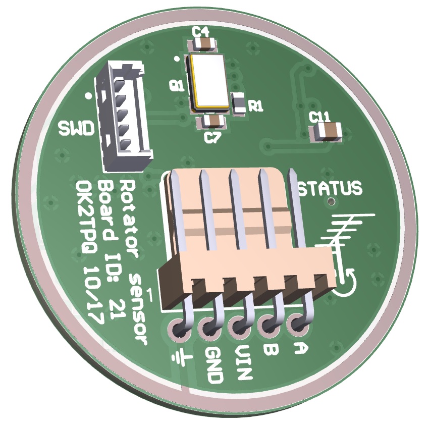
Aluminium enclosure by OK2IFS - web
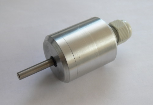
3D printable enclosure by OK1UGA - web
